L10 Bearing Life Calculation Formula with Worked Example for Bulk Orders

L10 Bearing Life Calculation Formula with Worked Example for Bulk Orders
L10 life is not a warranty; it is a statistical probability.
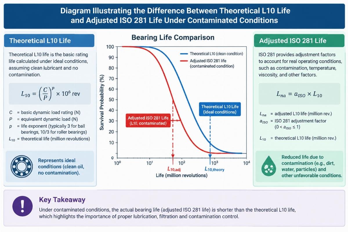
The Bearing Life Calculation L10 Formula provides a theoretical baseline for 90% reliability under ideal laboratory conditions, but real-world field environments require adjustment factors to prevent premature failure. Relying solely on the basic equation without accounting for contamination, shock loads, or lubrication quality leads to significant miscalculations in maintenance planning and inventory procurement.
I learned this distinction the hard way during a supply project for a nickel mine in West Africa. The client’s engineering team strictly followed the standard Bearing Life Calculation L10 Formula for their bulk order of spherical roller bearings, ignoring the extreme dust ingress and high-impact shock loads characteristic of their crushing circuit. The bearings failed prematurely, causing severe downtime that far exceeded the cost savings from the initial selection. This experience shifted my approach from merely quoting part numbers to analyzing actual field conditions before finalizing any technical specification.
Understanding the gap between textbook math and operational reality is critical for distributors and MRO operators who need to ensure equipment uptime.
What is the L10 Bearing Life Formula?
The L10 formula defines the number of revolutions a bearing can complete before 10% of a group of identical bearings fail under constant load.
This metric, often referred to as rating life, is based on the fatigue limit of the bearing material. It assumes perfect mounting, ideal lubrication, and clean operating conditions. The fundamental equation is:
$$L_{10} = left( frac{C}{P} right)^p$$
Where:
- $L_{10}$ is the rating life in millions of revolutions.
- $C$ is the basic dynamic load rating provided by the manufacturer [NEED_CITE: definition of basic dynamic load rating per ISO 281].
- $P$ is the equivalent dynamic bearing load.
- $p$ is the exponent (3 for ball bearings, 10/3 for roller bearings).
Many buyers mistakenly interpret L10 as the guaranteed minimum lifespan. In reality, it is a statistical threshold. If you operate ten identical bearings under identical ideal conditions, one is expected to fail by the time the group reaches the L10 life point. The other nine may last significantly longer. This statistical nature means that L10 is useful for comparing bearing sizes but insufficient for predicting exact replacement intervals in harsh industrial settings.

For bulk orders, understanding this baseline is the first step. However, stopping here ignores the variables that actually destroy bearings in the field.
How to Calculate Equivalent Dynamic Load?
Accurately combining radial and axial forces is critical for determining the correct equivalent dynamic load (P).
Most industrial applications do not subject bearings to pure radial or pure axial loads. Instead, they experience combined loading. Using only the radial force in the Bearing Life Calculation L10 Formula will drastically overestimate the bearing’s life if significant axial loads are present.
The equivalent dynamic load $P$ is calculated using:
$$P = X cdot F_r + Y cdot F_a$$
Where:
- $F_r$ is the actual radial load.
- $F_a$ is the actual axial load.
- $X$ and $Y$ are calculation factors that depend on the bearing type and the ratio of $F_a / F_r$ [NEED_CITE: calculation factors for combined loads per manufacturer engineering manuals].
| Load Condition | Radial Factor (X) | Axial Factor (Y) | Impact on Life Calculation |
|---|---|---|---|
| Pure Radial Load | 1 | 0 | Baseline calculation |
| Combined Load (Low Axial) | >1 | >0 | Moderate life reduction |
| Combined Load (High Axial) | >1 | >>0 | Significant life reduction |
A common error observed in regional distribution centers is assuming that a higher basic dynamic load rating ($C$) compensates for incorrect $P$ values. It does not. If the axial component is ignored, the calculated $P$ is too low, making the ratio $C/P$ artificially high. This results in a predicted life that is multiples of the actual operational life. For spherical roller bearings, which are often used in heavy-duty applications, the axial factor $Y$ can be substantial, making precise load assessment mandatory.

When reviewing technical datasheets for bulk procurement, always verify that the equivalent load calculation accounts for all force vectors present in the specific machinery application.
Step-by-Step Worked Example for Spherical Roller Bearings
Walking through a practical calculation reveals how raw data translates into millions of revolutions.
To demonstrate the Bearing Life Calculation L10 Formula, consider a spherical roller bearing used in an aggregate crusher. This example highlights the mechanical process before applying environmental adjustments.
Step 1: Identify Basic Parameters
Assume a spherical roller bearing with a basic dynamic load rating ($C$) of 500 kN. The application involves a radial load ($F_r$) of 100 kN and an axial load ($F_a$) of 50 kN. For this bearing type, let us assume calculation factors $X = 1$ and $Y = 2$ based on the manufacturer’s table for the given load ratio [NEED_CITE: typical calculation factors for spherical roller bearings].
Step 2: Calculate Equivalent Dynamic Load (P)
$$P = (1 times 100) + (2 times 50) = 200 text{ kN}$$
Step 3: Apply the L10 Formula
Since this is a roller bearing, the exponent $p$ is $10/3$ (approximately 3.33).
$$L_{10} = left( frac{500}{200} right)^{3.33}$$
$$L_{10} = (2.5)^{3.33} approx 21.5 text{ million revolutions}$$
Step 4: Convert to Operating Hours
If the crusher operates at 600 RPM, the life in hours is:
$$text{Life (hours)} = frac{21,500,000}{600 times 60} approx 597 text{ hours}$$
This result might seem surprisingly low for a heavy-duty bearing. However, it reflects the high impact of the axial load and the steep exponent for roller bearings. A small increase in load would drastically reduce this figure. This bearing life formula worked example illustrates why simply selecting a bearing with a high $C$ value is not enough; the load ratio must be optimized.

This theoretical value serves as the starting point. Without further adjustment, it remains a laboratory figure.
Why Does Real-World Life Differ from L10?
Field contaminants and shock loads drastically reduce actual lifespan compared to theoretical math.
The standard Bearing Life Calculation L10 Formula assumes clean, well-lubricated conditions. In reality, industrial environments introduce variables that accelerate fatigue and wear. The ISO 281 standard introduced modification factors ($a_{ISO}$) to account for lubrication quality, contamination levels, and fatigue load limits [NEED_CITE: ISO 281 modification factors for adjusted rating life].
Consider a cement plant in the MENA region. The ambient temperatures are extreme, and the dust load is continuous. Even if the L10 bearing life calculation example predicts thousands of hours, the ingress of fine particulate matter acts as an abrasive in the lubricant. This leads to surface distress and premature spalling. In such cases, the effective life may be derated significantly unless sealed bearings or superior filtration systems are employed.
Another case involved an OEM for aggregate crushers. By upgrading to heavy-duty sealed bearings based on modified life calculations rather than basic L10, they achieved a substantial extension in service intervals. The key was recognizing that the standard formula did not account for the shock loads inherent in crushing operations. Shock loads create peak stresses that exceed the fatigue limit, rendering the standard L10 prediction optimistic.
| Environmental Factor | Impact on Bearing Life | Mitigation Strategy |
|---|---|---|
| Contamination (Dust/Dirt) | Noticeably reduced | Sealed bearings, improved housing seals |
| Poor Lubrication | Substantially extended risk | Automatic lubrication systems, high-viscosity grease |
| Shock Loads | Unpredictable failure | Heavy-duty cages, increased safety factor |
| Misalignment | Accelerated wear | Self-aligning bearings, precise mounting tools |
When clients request bulk orders based solely on a basic spherical roller bearing L10 calculation, I recommend a review of the operating environment. Technical selection support can help identify whether standard open bearings are sufficient or if sealed, heavy-duty variants are required to match the adjusted life expectations. Ignoring these factors negates the benefits of higher load ratings.

Real-world durability depends on aligning the theoretical calculation with the physical realities of the installation site.
Conclusion
Theoretical calculations provide a baseline, but field conditions dictate actual performance.
The Bearing Life Calculation L10 Formula is a vital tool for initial sizing, but it must be supplemented with environmental adjustment factors to be useful for maintenance planning. By accurately calculating equivalent loads and accounting for contamination and shock, operators can avoid premature failures and optimize their inventory strategies.
Need a quote for the bearings in this article?
Send your part numbers and get price, stock and lead time within 4 hours.

Written by
authorEditor covering global sourcing, supplier verification, and industrial product knowledge. Content is compiled from manufacturer specifications, industry standards, and hands-on experience with international B2B buyers. Every article is fact-checked before publishing to help procurement professionals make informed decisions.
View all posts

